Symbol Standarisation P&ID For Industri Standard piping and instrument symbols are detailed diagrammatic documentation that provides a set of forms & standards for documenting P&IDs and PFDs, including standard shapes for instruments, valves, pumps, heat exchangers, mixers, crushers, vessels, compressors, filters, motors and other connection forms. Here are some symbols on P&ID : So, those are some of the symbols that we will often see when reading piping & instrument diagrams. May be useful.
Current Or Ampere
What is Ampere (A) ?
Before we discuss further about current or amperage, we will first discuss a little about atoms.
Atom
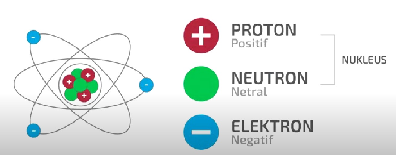
Every object that is around us is composed of small particles called atoms, within the atom itself there is a nucleus and several electrons (negatively charged) that surround it. The nucleus itself consists of several protons (positive charge) and neutrons (neutral), this makes the atomic nucleus positively charged, while the electrons surrounding the nucleus are negatively charged.

Atomic Movement
Negative charges will push or repel other negative charges, while positive and negative charges will attract each other if they are close together. So an electron will push another electron if it can move freely.
In objects such as wood and plastic electrons cannot move freely, so they cannot conduct charge or electricity. But in materials that conduct electricity, such as iron and copper, the electrons can move freely, while the nucleus is fixed. Electrons in iron or copper can move from one atom to the next atom, if an electron moves from one atom to another then the target electron will also move to the next atom, these electrons move very fast approaching the speed of light. The flow or movement of electrons is what produces an electric current.
Then what is an ampere?, the ampere symbolized by the letter (A) is a unit of the number of electrons that flow to a point per second.
1 Ampere = 6.24 x 10*18 electrons flowing per second
or
1 Ampere = 1 Coulomb of charge flowing per second
In short, Ampere (A) is the unit for electric current, while the electron charge is measured in coulombs.
The electrons in the cable or conductor cannot move on their own, they must be driven by energy, the potential energy that drives electrons to move we know voltage or voltage, for a discussion of voltage or voltage we will discuss in the next post, yes.
The electrons move because of the energy of the voltage and move to flow towards the load, the electrons move in a closed unbroken path. What we know now is that electrons move from positive poles to negative poles (for DC current circuits), but in fact electrons move from negative to positive, then the energy of these electrons is converted into other energy such as heat or light.
Electrons will continue to move from negative to positive continuously. If in this circuit the load is removed then the negative charge directly meets the positive then there will be an energy collision, or what we call a short circuit.
The term ampere itself is taken from the name of a French scientist named Andre Marie Ampere, one of the discoverers of electromagnetism in 1775 - 1836.
Alright, that was a brief introduction about amperage, if something isn't quite right, don't hesitate to correct it in the comments column.
Comments
Post a Comment